Some Basics on Reflow Soldering
Why Reflow?
Because it is easy, fast, reliable and gives professional results with very little skills to master.
While many SMD components can be soldered with just a standard iron this is generally a very slow process. It also requires some skills to be able to solder smaller components and high-density pins.
Some footprints like QFN are very difficult to be soldered with an iron even for a trained technician and often those joints are not good enough even for prototyping purposes. BGA components are of course impossible to deal with and for them a reflow oven is a must.
Reflow ovens are the first choice in the industry for production and prototyping, the only downside are their cost and the costs related to reflow technique: you are going to need a stencil for every board and you need to use solder paste which is generally quite expansive.
Lately these costs, thanks to some Chinese production facilities and resellers (like Elecrow, SeeedStudio, ITead, etc…), have been lowered from several hundreds of dollars for a steal stencil to less than 20 USD, allowing even hobbyists to build devices with modern and difficult footprints.
The only high cost device to buy is a reflow oven.
Industrial ovens usually costs more than 1.000 USD and the cheaper Chinese alternatives on the market (which still are quite pricey, around 400/500 USD) are simply too buggy and do not have a build quality good enough for a reliable (and secure) use.
A toaster oven conversion is usually a much cheaper (and often better) alternative, but to be able to control the temperature to follow the suggested thermal profiles you are going to need a controller capable of compensating for the high thermal inertia usually related to cheap mass produced food ovens.
These toaster ovens also transmit heat mostly by radiation than convection and this is another factor to take into account when building a controller.
X-toaster has been designed to follow any reflow profile, to be adaptable to any oven and to compensate for inertia and hysteresis.
Things to Know
When dealing with reflow soldering there are some things to know which usually are not needed when hand soldering with an iron.
Moisture Content
The first is that some components are sensible to thermal chock and the moisture content of their packages may be an issue.
When you order some big microcontroller from Digi-Key or Mouser they usually come in a sealed bag with a humidity indicator and a desiccant pack inside. That’s because the moisture in the package when exposed to high temperatures vaporizes and, if you do not give this vapors enough time to exit the package, the result could be a cracked microcontroller.
This lead to the first rule: only open these packing when you are going to solder them on the PCB and check the indicator that the moisture has not gone over the maximum allowed percentage.
If you have a lot of components to be soldered in many PCBs during more than one day, always use an ESD safe sealed bag and keep them in it, with the indicator and the desiccant. If you have some sensible components sitting in a box for more than a few days you should try to let the moisture in it evaporate gently before attempting any reflow.
X-toaster comes with a preprogrammed desiccant profile to keep the components at 125°C for 60/90 minutes.
Even so keep in mind that this is not an ideal process and that micro fractures could be forming.
Hot and Cold Spot
It may be quite difficult, even with big professional ovens, to keep a uniform temperature across the entire PCB.
When using a toaster oven this problem can cause some serious issues like pads where the solder paste do not reflow correctly or, even worst, components which overshoots the target temperature.
Moreover, since in the toaster ovens the heat is transferred mostly by radiation, remember that bigger black components heats faster than smaller ones. Ideally you should measure temperature over the entire board and across every component to be sure to have a profile with a peak temperature high enough for reflowing but not too high to cause thermal shock on the bigger components.
Of course this is not very practical and you should be ok by following a couple of simple rules:
If you get unsoldered pads but you are already hitting peak temperature try to make your profile last a little longer for every phase (while keeping it inside the maximum limits). This is usually enough to have the entire board heat mostly at the same temperature.
A convection fan may help in spreading the heat with more uniformity: if your oven have one make some experiments turning it on for one or more phases of your profile.
Check the tray you are using to sit the PCB inside the oven. The standard toaster oven tray (simply made with steel bars) sometimes absorbs too much heat and you get cold strips where the PCB come in contact with the tray bars. If this is your case build another tray with some steel mesh or try to raise the PCB from the tray with some metal spacers.
When designing your board keep in mind that large ground planes absorb much more heat and inertia may cause the pins sitting directly on these planes to overshoot. If you have such problems do not put your pads directly over these planes. Instead connect them with short tracks and eventually try to use thermal reliefs.
Leaded and Lead-Free
Until a few years ago, every solder joint were made with Sn-Pb alloys and everyone where quite happy about it.
Then someone started to think about all the electronics discarded in the bin every day by billions of people and the consequent lead pollution.
This (and a few other reasons) brought to the concept of RoHS and lead-free electronic and the Sn-Pb was substituted with other alloys like Sn-Ag-Cu.
Today leaded solder is not allowed by laws of many countries, particularly in the European Union and, even if you live in a country where leaded solder medium are allowed, you should consider using lead-free solder paste.
Lead poisoning is something you should be concerned about, especially if you work in a home-lab.
When absorbed by your body, lead is a cumulative poison affecting your health in several nasty ways.
Lead poisoning is not easy to recognize and children are particularly vulnerable to lead, which impede their brain development.
The main problem in using lead-free solder paste is the higher temperature needed for reflowing.
When using lead-free pastes you need to use profiles with high peak temperatures (around 250°C) and you have to take special care to make sure that overshoots are kept to a minimum and timings are carefully respected to avoid damages to your PCB and components.
When programming your reflow profiles, you should refer to the suggested profiles published by the producers of your solder paste and by the manufacturer of the components of your board.
If you have no access to those documents and for general reflow applications you can always use the standard profiles published by JEDEC.
JEDEC Standard Profiles
The JEDEC Solid State Technology Association, formerly known as the Joint Electron Device Engineering Council (JEDEC), is an independent semiconductor engineering trade organization and standardization body.
They published a few documents on reflow soldering with a couple of leaded and lead-free standard profiles you can refer to when programming X-toaster.
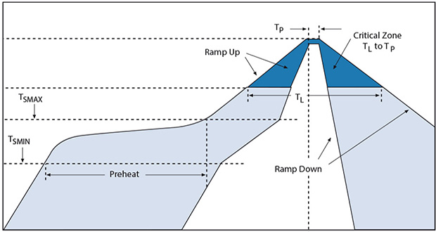
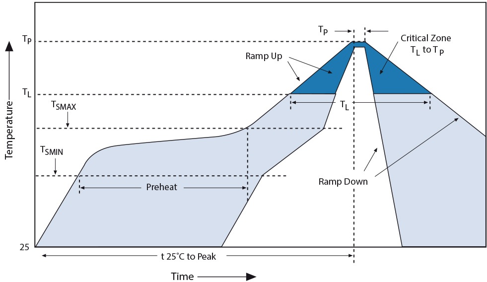
By looking at the graph (JEDEC/IPC J-STD-020) you can easily understand that there is not a strict curve to follow, instead there are areas where to fit you profile.
Even peak temperature (Tp) is not fixed for every situation, but changes depending on the packages thickness and volume.
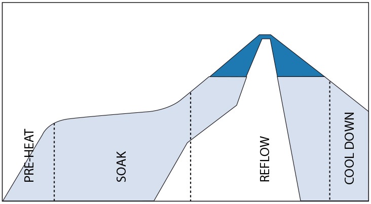
When programming the nodes on X-toaster these will be the corresponding phases:
PREHEAT
Flux solvent are evaporated during this phase and your board is quickly brought to a little bit more than half reflow temperature
SOAK
Solvents evaporation completes during this phase. Flux starts its deoxidizing action on parts to be joined and board is kept to an almost stable temperature for a certain amount of time to minimize thermal gradient
REFLOW
In the blue zone there is the actual melting of the alloy which forms the mechanical/electrical joint
COOL-DOWN
A quick cooling would be desirable to create finer grain structure and stronger joint. This is actually not always possible with toaster ovens where there are no exhaust/cooling fans. All you can do is simply open the oven’s door and wait until the temperature is low enough.
LEAD-FREE Parameters
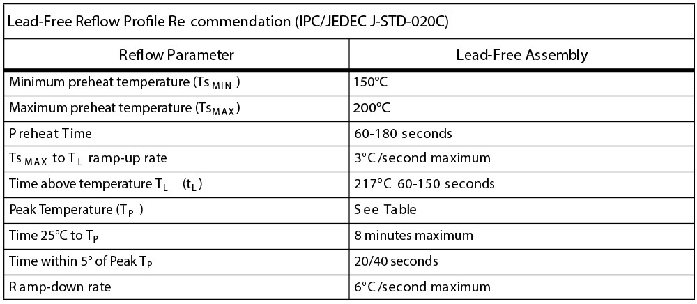
On the table we can identify the maximum ramp up and ramp down rate (3°C/s and 6°C/s respectively) which, in our case, are not a big problem because you will hardly be able to obtain steeper rates with toaster ovens.
What may be a problem instead are maximum time above liquidus (217°C, 60-150s max) and maximum time within 5°C of peak (Tp).
If your oven is not powerful you could be forced to increase those values to allow temperature to raise enough. That is why choosing a powerful and small (quick) toaster oven is so important for reflowing. You should be able to reach more than 1°C/s when ramping up (ideally at least 1.5°C/s) with your oven.
If you can’t you should consider another oven or adding more heating elements.
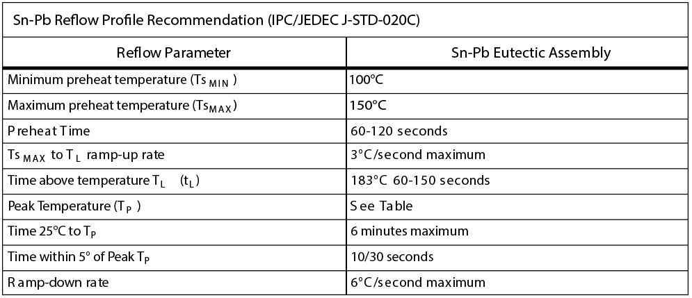
Sn-Pb Parameters
As expected Sn-Pb parameters are much more “relaxed”.
The most important factor is the peak temperature of only 225/240°C compared to the much higher 245/260°C of the lead-free profile.
JEDEC recommends shorter time within 5°C of Tp and also shorter time above liquidus compared to the lead-free parameters, but if your application is not critical you should be ok with longer profiles.
If your oven is not powerful enough for lead-free alloys and you are not willing to change or mod the oven, Sn-Pb may be your only choice for reflowing.
Draw your Reflow Profile
We have seen that you have some kind of freedom to draw a profile suittable for your applications and your particular oven.
At this point you really need to know what is your oven capable of, what kind of solder paste you will be using and which component sizes will be mounted on your board.
Knowing the rate at which your oven can ramp up and cool down is easy enough using X-toaster controller.
After setting up your oven, controller and thermocouple like suggested in the article “X-toaster Installation & Wiring“, program a profile with a high Kp and a steep temperature rise (5s) to around 150°C and let it run for at least a couple of minutes or simply set the “Preheat until” parameter to 150°C. Your oven will be fired on constantly and you will be able to observe how much your oven is ramping.
For the cooldown you can do the same in reverse: at the end of the previous profile set a steep cooldown to 25°C and make it at least a couple of minutes long. When the last phase start, open your oven’s door fully and you can observe at which rate your oven is cooling.
You will probably find that your ramp up is around 1.5°C/s and you are cooling down at no more than 2 or maybe 3 °C/s.
It would be pointless to program a profile which your oven will never be able to follow. Make sure to use the previous limits as a reference.
If you find that your oven is a little bit slow in the pre-reflow ramp-up you can tweak your profile to make that ramp a little bit easier, for example by using the whole allowed limits for the SOAK phase (150°C-200°C for lead-free and 100°C-150°C for leaded).
Special care should be dedicated to the peak temperature.
Once you know which peak temperature you a targeting based on your components size, draw a profile which respect the maximum time allowed for it and run a test.
If you can, diminish the time within Tp as much as possible. If you observe overshoots try to use the Overshoot Compensation feature in the ADVANCED options.
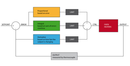
Of course you should also set the PID parameters. These are addressed in the “PID Tuning” article.
